Significant work is needed to enable continuous manufacturing for challenging chemistries
Continuous manufacturing offers many advantages over traditional batch-wise processes – including increased system control and less variation in product quality – especially in the pharmaceutical industry. As such, the U.S. Food and Drug Administration encourages research into continuous manufacturing as a means of improving drug quality, and manufacturers anticipate improvements in process economics. While recent efforts to move commercial production toward a continuous setup is promising, significant work is needed to reach end-to-end continuous manufacturing, especially for challenging chemistries. The design of new continuous unit operations for product isolation and catalyst recovery is necessary to realize fully continuous processes that involve difficult or coupled chemistries and separations.
Magnetic separation technique can recover and recycle >99.9% of immobilized enzyme catalyst
To address these needs, researchers designed a magnetic separation device and technique to continuously separate biofunctionalized catalyst particles from a solid, crystalline product. Magnetic force is used to enhance traditional solid-solid separation techniques to yield a high-purity product stream and continuously return catalyst to a reactor. The separator can recover and recycle >99.9% of immobilized enzyme catalyst to the continuous reactive crystallizer, while simultaneously yielding pure amoxicillin through coupling of separators in series and a catalyst trap. As both continuous pharmaceutical processes and reactive crystallizations are gaining traction, this technology could help accelerate the adoption of continuous, heterogeneously catalyzed reactive crystallizations and, more generally, expand the chemistries and processes amenable to continuous manufacturing.
- Continuous flow: The device is capable of continuous separation for multiple hours and can be parallelized or ran in series to improve both solids throughput and separation efficiency. The effective solid size range that is capable of separation is between 10 and 500 μm. The device can process >10 g solids per hour and can achieve a separation efficiency of >99% in a single pass.
- Cost-efficient: This technology reduces costs by using 3D-printed materials and neodymium magnets.
- Solid-solid separation: The technique allows for a continuous flow and solid-solid separation of particles, including those identical in size, provided that one particle is magnetic or responds to a magnetic field.
- Expanded scale: Magnetic force has been used as the driving force for separations on both large and small scales but has yet to be applied continuously at an intermediate scale. This technology addresses that gap and expands the applicability of magnetic separations to include biocatalytic and continuous processing applications.
- Wide size distribution: The most similar existing device is a field-flow fractionator, which is used to continuously sort paramagnetic nanoparticles based on size. In contrast, this device is designed to separate magnetic catalyst microparticles from crystalline product with a wide distribution of sizes.
The technique and device are applicable to manufacturing processes and are particularly beneficial in the pharmaceutical industry.
- This device is useful for solid-solid separations where one solid responds to a magnetic field and the other is non-magnetic. Separations of solids in the 10 μm to 500 μm range would particularly benefit from this device.
- The methods for designing similar magnetic separation systems could be applied to other continuous, heterogeneously catalyzed, solids-forming reactions.
- Further optimization of the device could enable use for a wider range of particle sizes by tuning the device volume, shape, and magnetic force applied to the system.

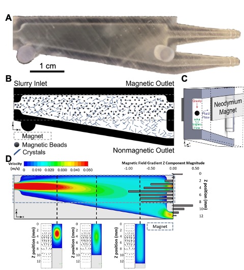
Magnetophoretic separator design and simulation. (A) A single separator device. (B) Cross section of device showing placement of neodymium magnets on the top half of the device and the gravitational, magnetic, and fluid flow forces acting on solid particles within the device. (C) Schematic of anticipated flow of particles through the device. Magnetic particles remain above the magnet placement and are funneled to the magnetic outlet (top) while crystals settle out toward the nonmagnetic outlet (bottom). Some fraction of crystals remains distributed throughout the fluid and exit the magnetic outlet with recycled magnetic particles. (D) Simulation of the separator showing fluid forces as well as the magnetic field gradient magnitude generated by placement of magnets on either side of the device. Cross sections (below) show general trends in the x-direction for both magnetic field gradient vectors as well as fluid flow.

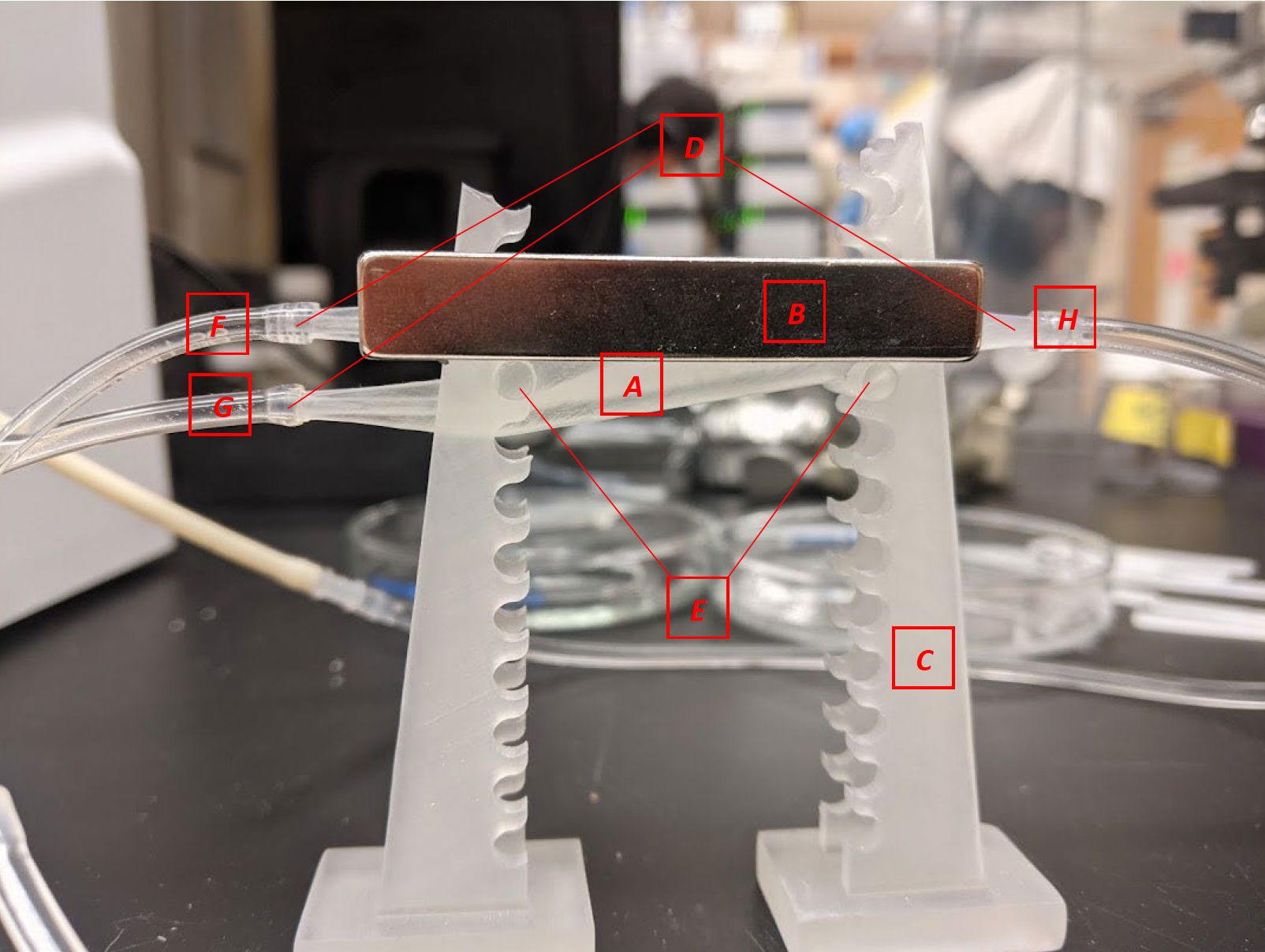
The magnetophoretic separator device, including (A) main separation chamber, (B) permanent magnets, (C) stand, (D) tapered connectors for flexible tubing, (E) mounting pegs, (F) outlet for magnetic material, (G) outlet for non-magnetic material, and (H) inlet.
