Cantilevered payloads are susceptible to shock loads
Installing small satellites often entails sliding a payload canister into a blind socket and bolting the front flange of the payload to the launch vehicle’s exposed structure. This creates an undesirable load path susceptible to shock loads (i.e., sudden increases in load), because the payload is most often cantilevered from the front flange, which results in higher stresses. These sudden shock loads are caused by gaps between the support and the sides of the socket, which are common with existing connection solutions that are unable to maintain consistent and direct contact.
Expanding payload support method creates a predictable load path
This expandable back drive–resistant wedge is a payload support system for limited-access environments, such as small satellite installations. By creating a more predictable load path, the technology eliminates potential damage to the payload due to sudden shock loading that can occur as a result of higher stresses from cantilevered loads. Expanding a wedge into the rails of the canister socket prior to inserting the payload generates the improved load path. By securing both ends of the payload, this approach creates a fixed-fixed beam load instead of a fixed-free cantilevered load.
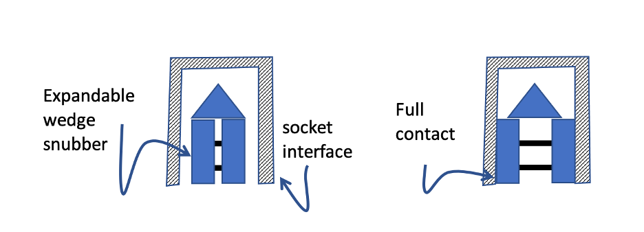
As shown in the first figure below, the expandable cartridge wedge has two straight, parallel arms (snubbers) with angled ends that meet at a central hub. The snubbers remain parallel, while a tapered key at the distal end is driven in remotely to expand the arms outward to contact the socket. Driving the tapered key remotely allows payload installation into a blind socket and still achieves a fixed-fixed load condition.
The wedge and snubber mechanism expand to adjust to the rail dimensions and securely close the gap between the rail and the payload. To predictably transfer lateral load, the snubbers make and maintain rigid contact with the socket walls throughout the duration of the mission. The expanding wedge generates load only up to the desired maximum.
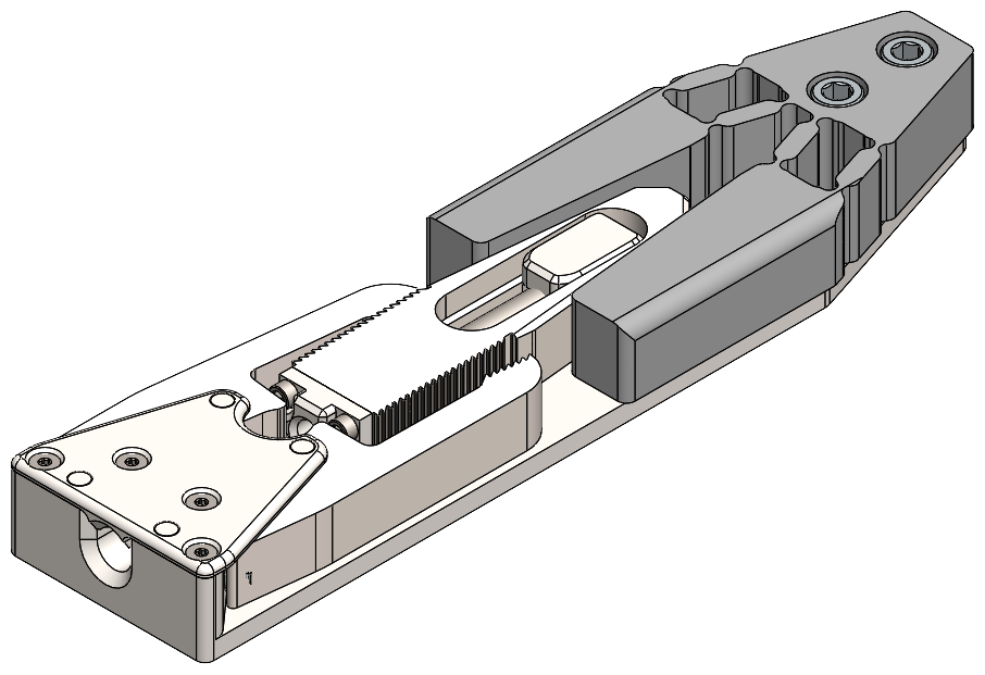
Additionally, two offset, spring-activated pawls make the cartridge resistant to vibration by holding the wedge in place after establishing proper contact. A specialized tool releases the pawls to allow system unloading and payload removal.
- Improves stability: The fixed-fixed beam in this expandable device greatly reduces system deflection when exposed to vibration and shock, improving overall system stability.
- Reduces damage: By creating a more predictable load path, this device reduces the chance of payload damage caused by vibration and the sudden shock loading that is more likely to occur due to the higher stresses of cantilevered loads.
- Back drive resistant: The spring-activated pawls hold the drive in place and prevent back drive that would loosen the payload.
- Small satellite installations
- Other limited-access applications that involve delivering and securing payloads:
- Removable vehicle-mounted payloads
- Truck-mounted electronics
- Aircraft electronics modules
- Rail-mounted storage systems
- Position retention for infinitely adjustable telescoping mechanisms

Left drawing shows a cross-section of the device in an unexpanded configuration. The vertical snubbers expand outward to secure the load in the chamber. The drawing to the right shows the device expanded, with the snubbers making full contact with the socket rails.

Detailed device drawing showing entry point at the distal end for the installation and removal tool, pawls for preventing back drive, and parallel snubbers.

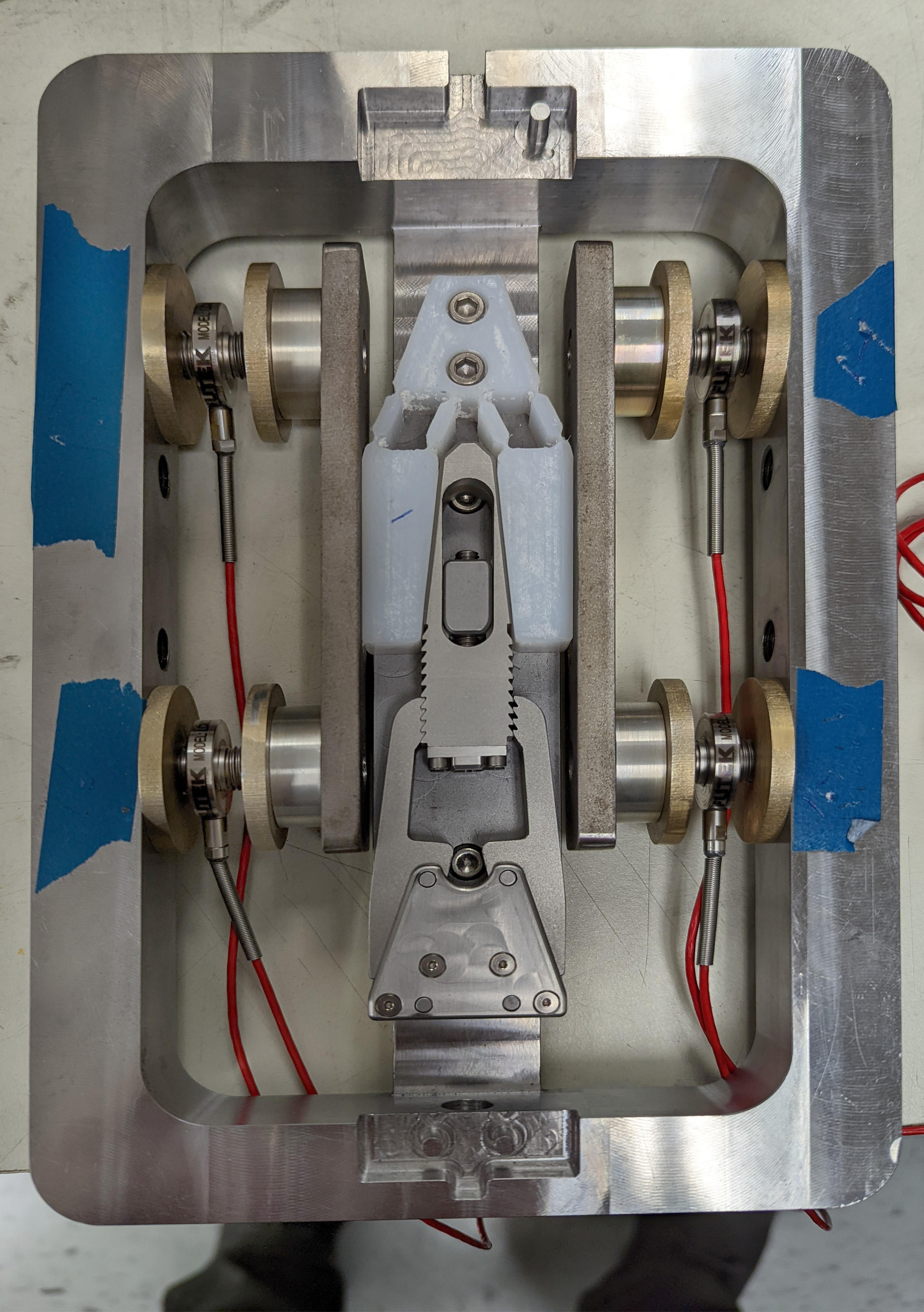
Device in a test fixture, simulating the rails of a socket, with snubbers slightly expanded to contact socket rails.
